Naich

Beaks 2 and the Stupid Little Circuits

beaks.live finally got its update in 2025, a year late, and not as fancy as it was supposed to be. But it was bigger, it was better, and it had some seriously stupid circuits interfacing with the Raspberry Pi. Never has the phrase “if it’s stupid but it works, then it isn’t stupid” been pushed so far towards genuine stupidity.

A mess of electronics and wires
It’s not pretty but it works.

I’m assuming that you have some knowledge of how electronic circuits work, but hopefully you will get some idea of what is going on, even if you don’t. I feel there is a certain beauty in simplicity when it comes to electronics. Most electronics these days seems to be buying little black boxes that do things and plugging them into each other, with no knowledge needed of how they work. For example, I could have bought a D/A chip with an I2C interface and just plugged it into the Pi, but I have op-amps and transistors lying around, and it was far more rewarding to do a little bit of designing and some simple calculations to make a D/A out of the stuff in my junk drawers. This post is about the joy of keeping it simple and stupid.

The original beaks box was pretty cheap and nasty, and full of hacks – an off-the-shelf box, a terrible quality webcam with no sound, hardly any night vision, and a cramped living space, barely big enough to stretch your wings. I didn’t like being a slum landlord, so some thinking outside of the box was needed.

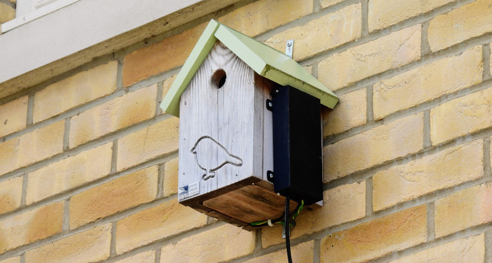
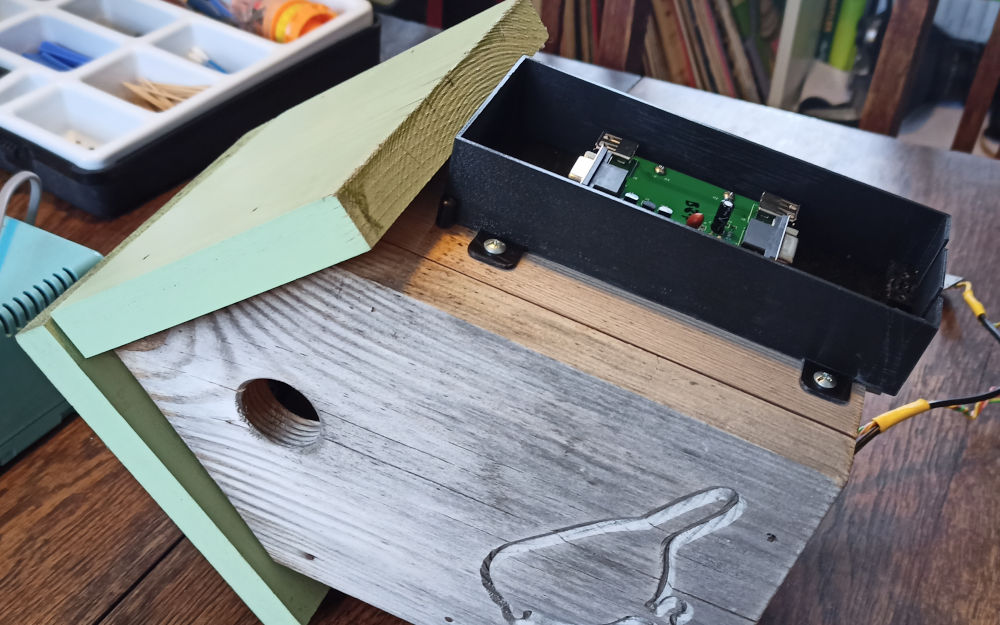
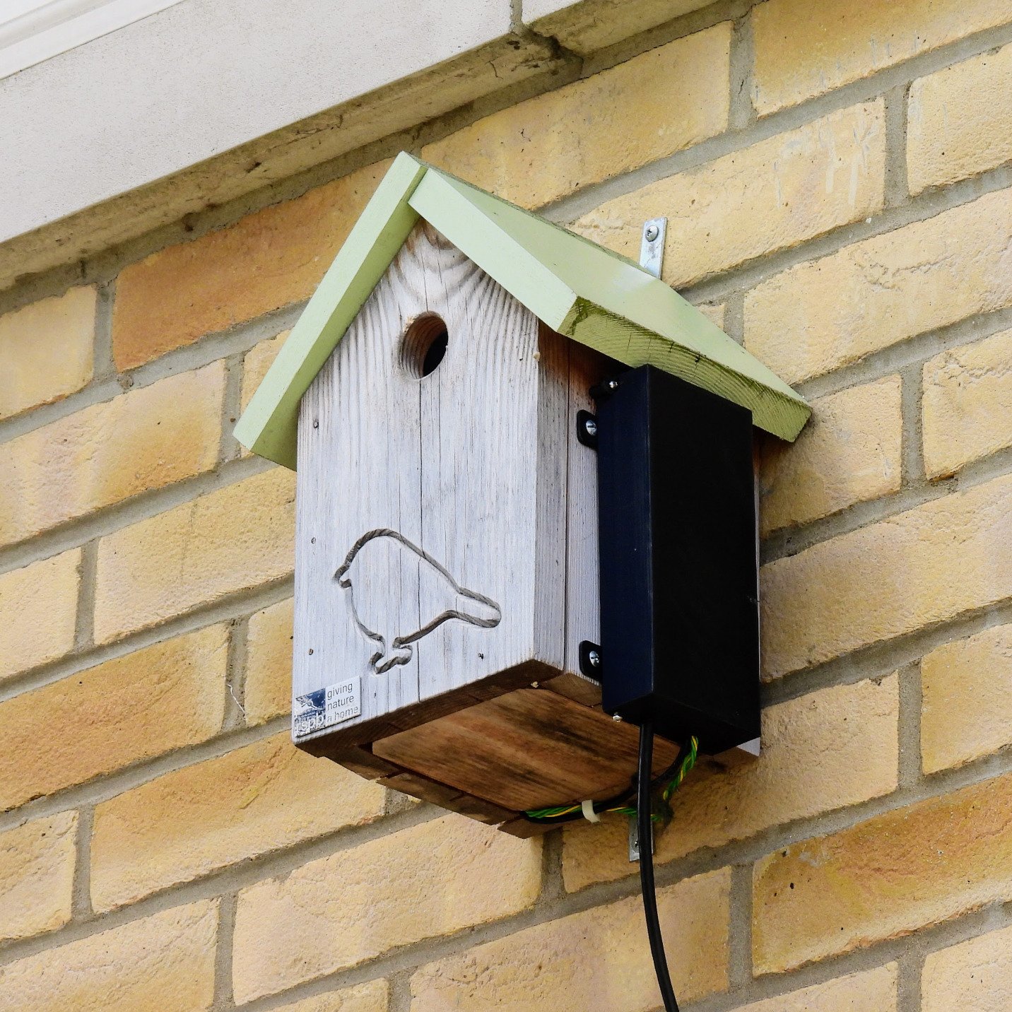
The outside of the box

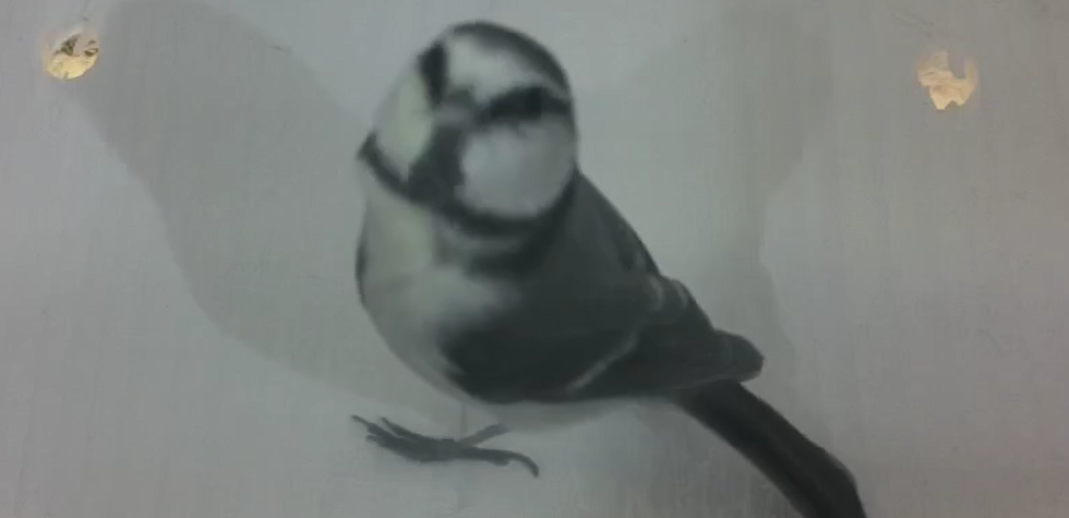
As well as increasing the size of the box, I wanted to watch the birds from a different angle. The original top-down angle means you miss a lot of the action – for example, when a parent is poking a grub down a chick’s throat, you only see the back of their head. A side view shows you details of the birds – I had no idea that their feet looked so weird. The camera also doesn’t want to be too close; improving the resolution and quality of the camera means you get the same amount of detail (in fact a lot more), even if the birds take up less of the frame. I didn’t want the bigger box to mean that some birds went out of shot because the view was too narrow.

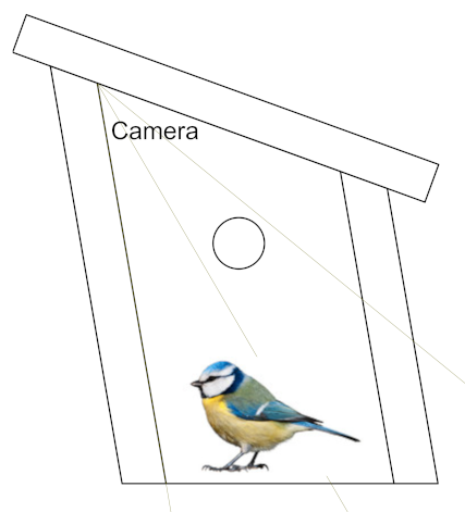
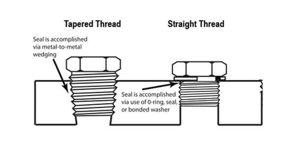
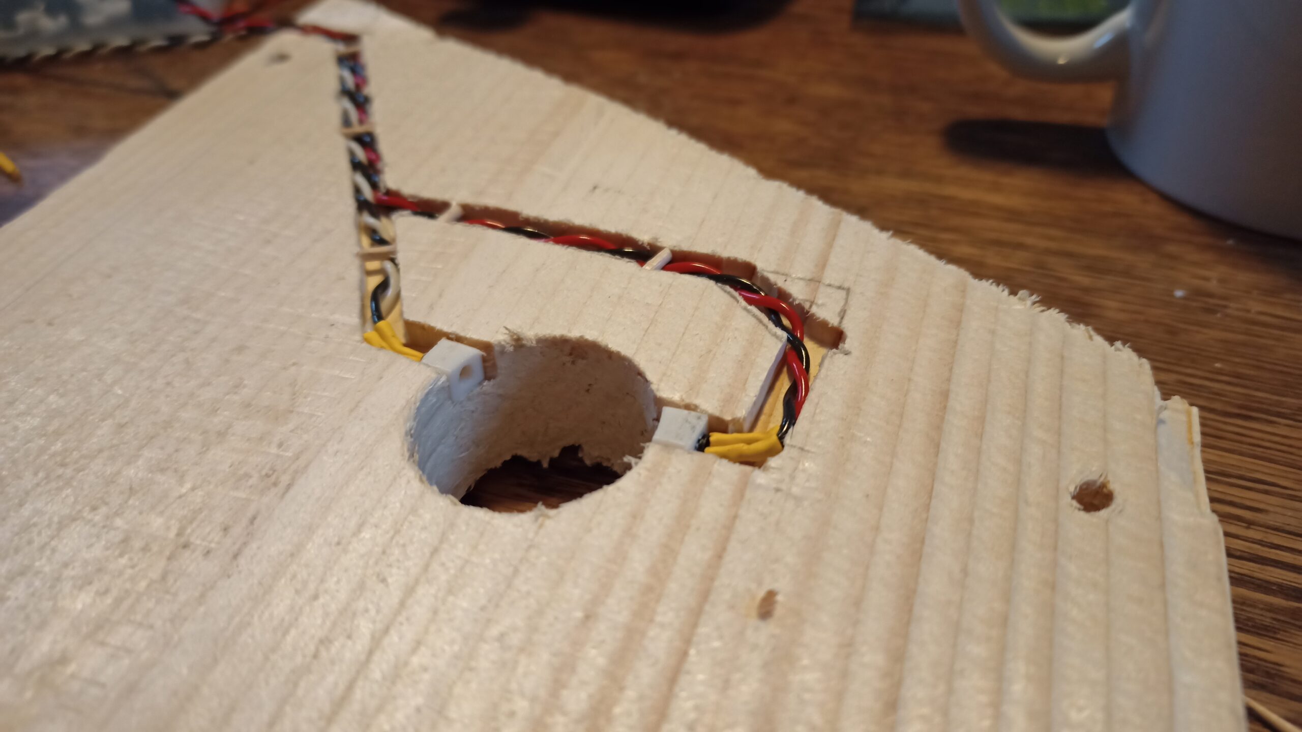
The design process gets a bit easier when you remember that birds don’t care about human aesthetics and are happy to nest in gnarled tree branches of any shape. The main consideration is the size of the hole in the front. The symmetry of the human-eye-pleasing one on the left below holds no benefits over the Skewbox / Slantbox / Italicbox / /box/ on the right.

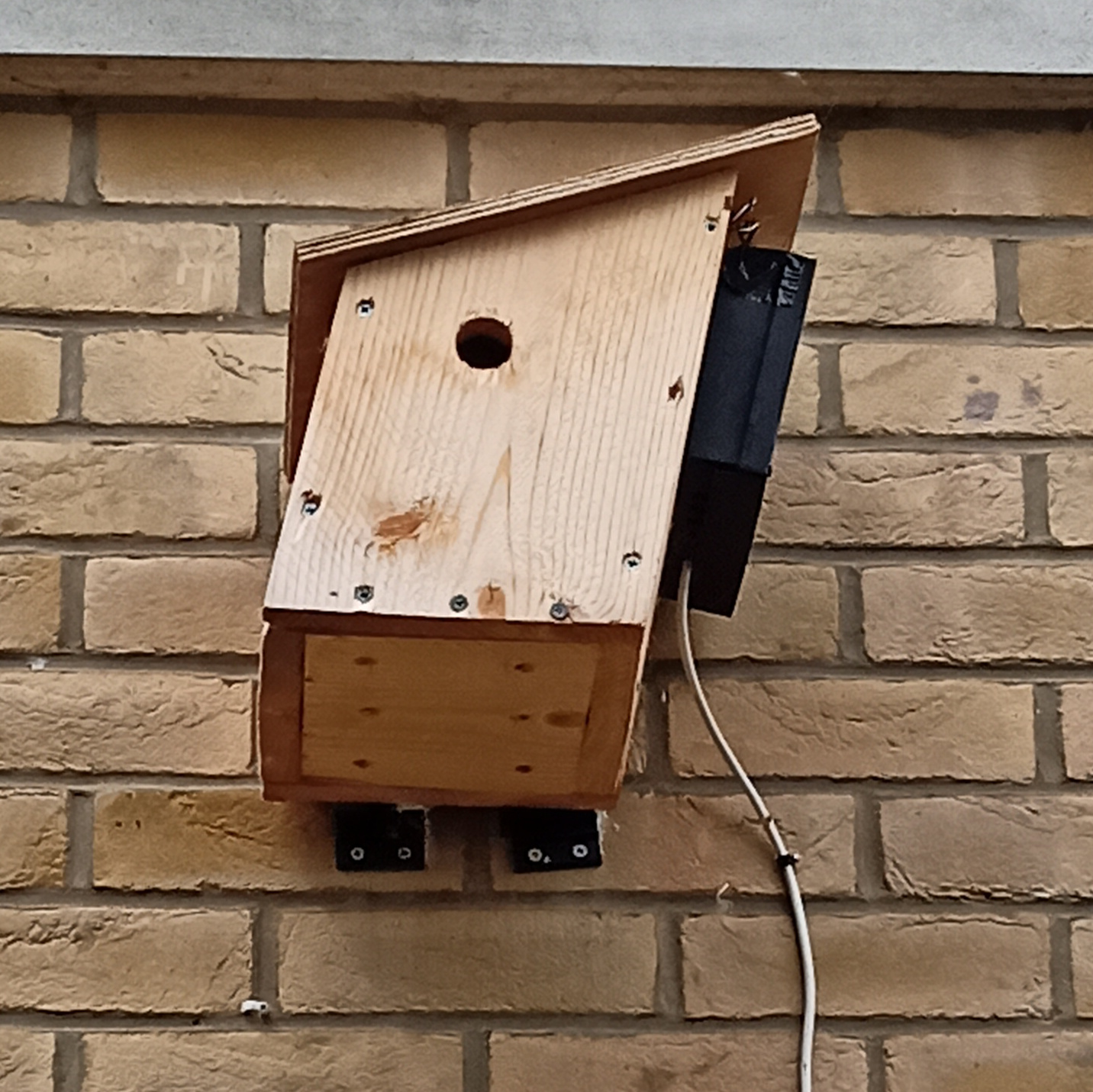
It’s wonky, it’s weird, it’s wugly, but it works.

Lights, Camera, Action!

The Raspberry Pi Camera Module 3 is a rather tasty little module which has an optional infra-red filter. The camera is very sensitive in the infra-red spectrum – more so than in visible light, so the filter basically makes it so colours aren’t drowned out by the infra-red. The original plan was to get one without the filter so I could light them up with infra-red light at night, and do the filtering in software to get something usable in daylight.

Turns out that they put physical filters on for a reason. The quality was so grim that it was just not possible to make it even remotely acceptable with software. I wanted to see blue tits, not smudgy grey tits. Still, at least they liked the box.

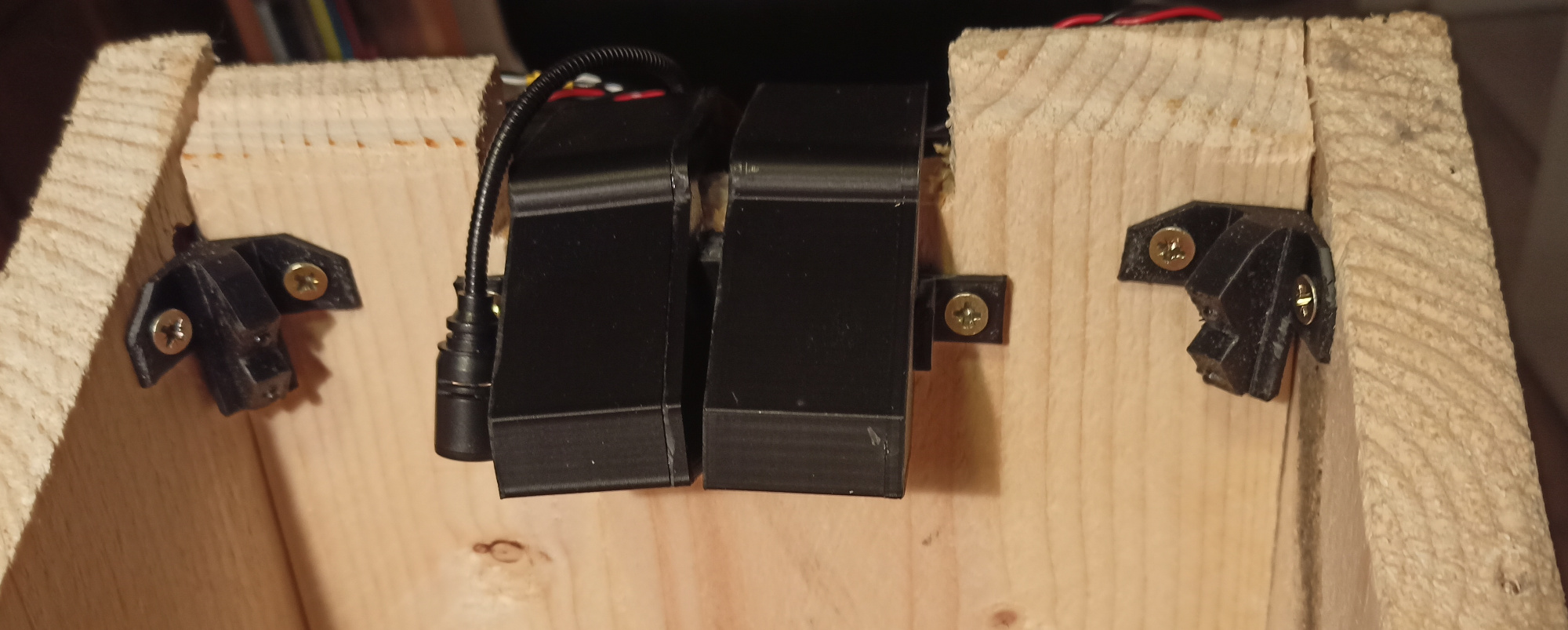
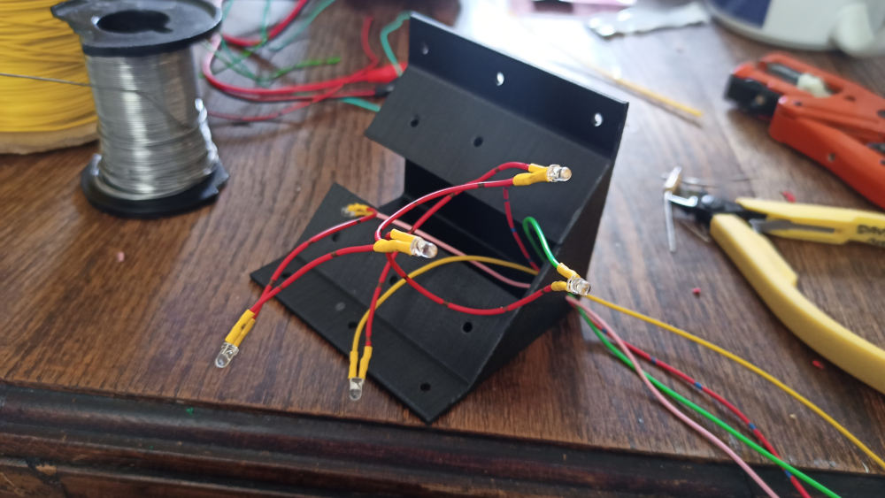
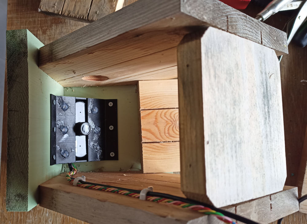
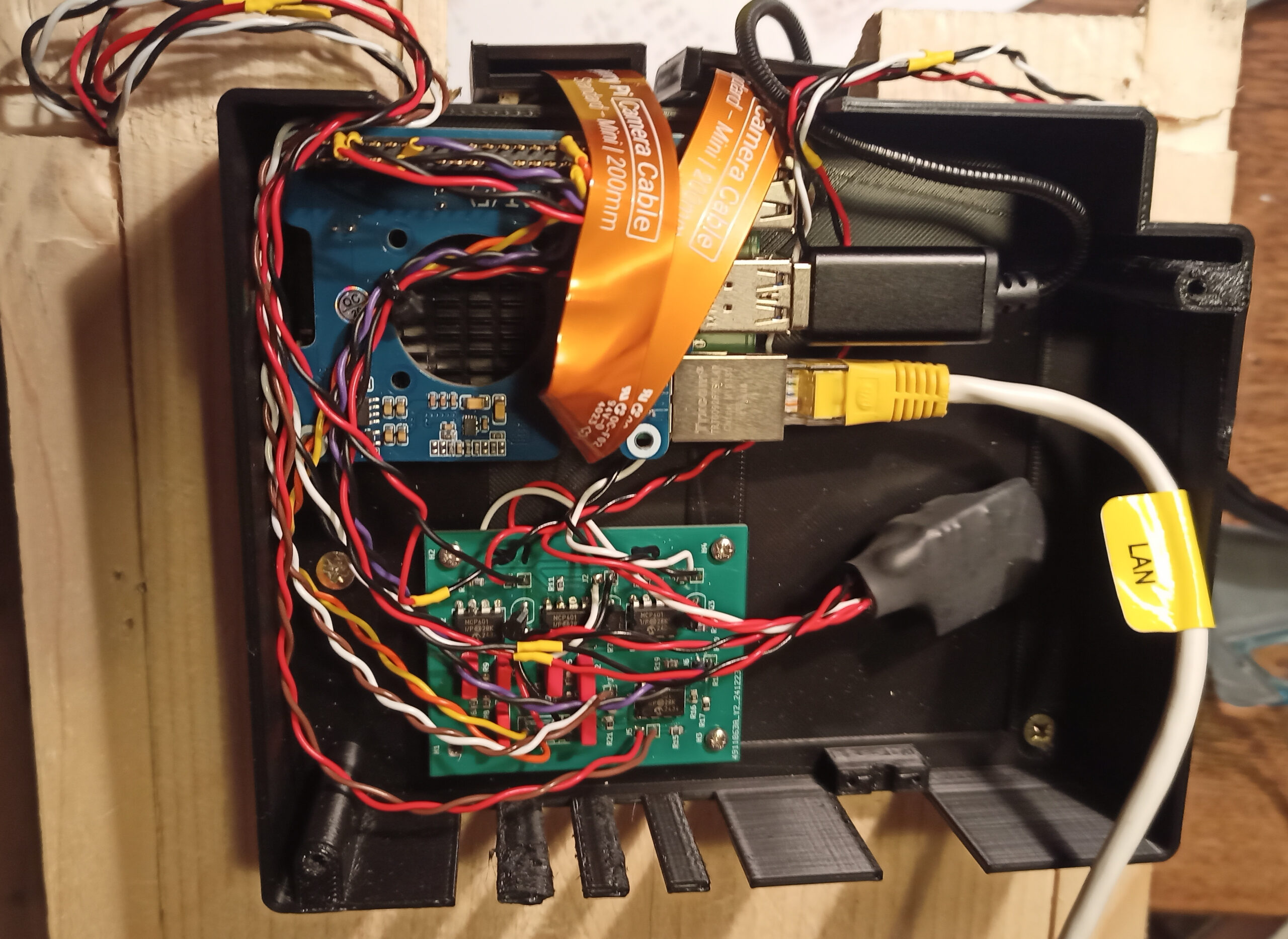
So, it had to be dual cameras – one for daylight, one for night-time infra-red illumination, seen here mounted in 3d printed cases and cunningly angled to have the same-ish view. To the left of it is the microphone, and in the corners are the LED lights – each with one white and one IR. Talking of LEDs, let’s look at the first stupid little circuit – a D/A converter and LED current driver. I hate buying stuff, so the main design consideration of any circuit I make is that it must be made out of bits I have lying around. This cheap and nasty D/A allows the Raspberry Pi to set the current going through the IR or white LEDs to anything from 0mA (out) to 19mA (full brightness):

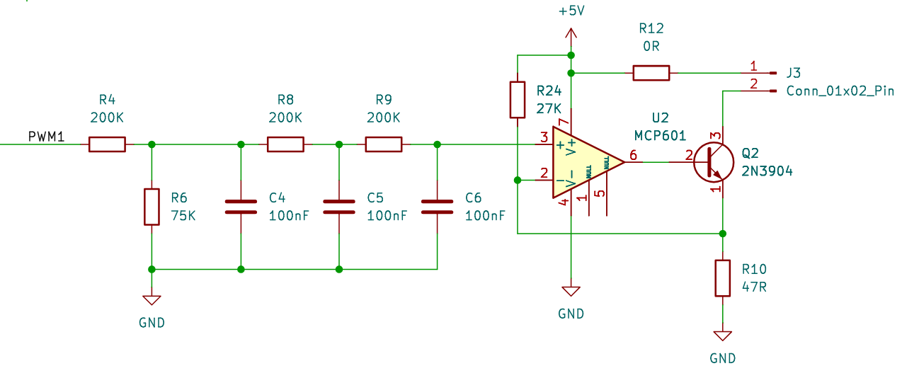
The LED goes on J3 and PWM1 comes from one of the Raspberry Pi’s Pulse Width Modulation outputs. So why the circuit above, rather than just sticking an LED on PWM1 and calling it a day? Although we can’t see the light flashing, it’s possible that the birds might and I didn’t want to make them think they were in a disco. It also might have caused problems with the camera, producing a strobing effect. R4/C4, R8/C5, and R9/C6 smooth out the pulses into a steady voltage. It’s a low pass filter, but in effect they convert the duty cycle of the output into a voltage between 0V and 0.9V.

So you have 0V – 0.9V going into the + input of the op-amp U2 with the – input connected to R10 and Q2 set up as a negative feedback current source. The inputs of the MCP601 can include ground, and although the output can go rail-to-rail, putting the LED on the collector side of Q2 means it doesn’t have to get anywhere close to V+. So we have 0.9V across R10 and 19mA (0.9V / 47R) flowing through Q2, and so also driving the LED at about the same current.

R24 is there to make sure that when the + input of U2 is 0V, there is a small bias voltage on the – input, clamping the output to 0V. This means we don’t have to worry about any input offsets in the op-amp keeping the LED turned on a little bit.

This circuit worked really well when I tried it in the living room. When it was attached to the side of the bird box, with the Pi being powered by power-over-ethernet, it flickered like a candle. The birds might have found this quite cosy, or they might have thought the box was on fire. By this time Mrs. B was almost moving in, so I couldn’t fix the problem then, and I just forgot about the white LEDs and drove the IR LEDs at 100%, which stopped the flicker. Since they all moved out, I have also not fixed the problem because I’m lazy. I’ve got about 4 months left to fix it before next year. Let’s face it – it’s quite unlikely it will ever be sorted out – 4 Months is not nearly enough procrastination time.

Fancy a bit of Light Metering?

The Raspberry Pi Camera Module 3 has all sorts of fancy exposure modes, so why not just use automatic exposure? The problem is in the nature of how the light gets into the box – almost exclusively through the entrance hole. On an overcast day the inside is lit fairly evenly, but on a sunny day you get a single blob of blindingly bright light, which moves across the box as the sun moves across the sky. This completely messes up any sort of automatic exposure – it either tries to average the bright spot with the rest of the dim box (too bright spot, too dim box) or set the exposure for the light blob (well exposed blob, black rest of box). I could not find a way of setting it up so it ignored the moving bright spot and set the exposure correctly for the rest of the box. The answer was to set the exposure depending on the general instensity of the light outside the box, using a light meter – a phototransistor that looked out of the house’s window next to the bird box, and an A/D to turn the intensity into a number.

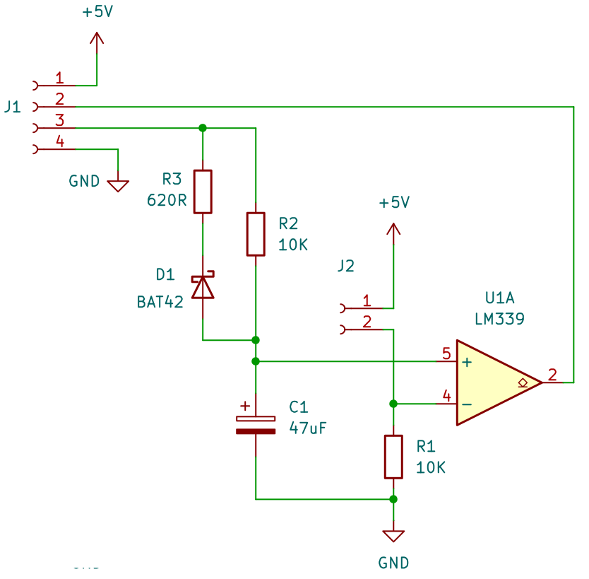
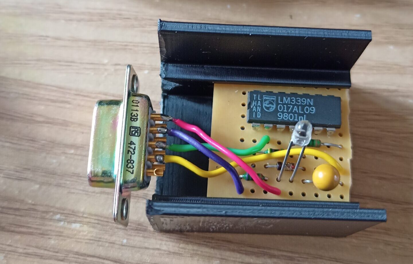
That there is a light meter, incorporating an A/D converter. Seriously. You put a phototransistor on J2, and plug J1 into a Raspberry Pi – pin 3 on a GPIO output and pin 2 on a GPIO input. I love this one because it’s so stupidly simple – you don’t even really need R3 and D1, so the component count can be as low as 5. The LM339 has an open collector output, and the Pi has pull-up resistors built in, so that’s another component saved.

The current through the phototransistor is proportional to the light hitting it – in this case I think it was 0.3mA in daylight, which corresponds to 3V on the – input of U1A. In order to measure this voltage, the Pi sets the GPIO output connected to J1/3 high and then the Pi measures how long it takes until the + input of the op-amp goes higher than the – input and J1/2 goes high. The time is proportional to the amount of light hitting the sensor.

Benefits of this type of A/D are:

  • Low component count.
  • Horribly innaccurate.
  • Unknown conversion time.
  • Long (we are talking large fractions of a second) sample time, getting longer the more accurate you want it to be.
  • You have to reset the Pi’s GPIO output on J1/3 to 0V and wait for C1 to discharge before you can do another sample. If you don’t wait long enough the next reading is garbage. R3/D1 speed this up a bit.
  • Non-linear measurements.

You might have noticed that only the first blob is an advantage, but the poor little fella looked lonely so I put all the disadvantages with him.

Of course, I’m not the first one to think of this, and you will usually see this sort of A/D with another op-amp used as an integrator (like the one on the right) to give a nice linear rise time on the capacitor. Because linear is better, right?

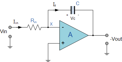
Well, in this case we can chalk one up to the stupid club because light isn’t linear. The exponential nature of light matches with the exponential nature of the RC charging circuit, producing a linear range that suits the exposure settings of the camera – which are non-linear to match the non-linear nature of light. Is this making sense yet, or do I have to say “non-linear” again? So, to take a light reading from your Pi:

  1. Record the system clock mS value.
  2. Set the GPIO output high.
  3. Loop round (I tried using interrupts, but it was easier to loop) until the GPIO input goes high or you have waited long enough.
  4. Subtract the current system clock mS value from the one in step 1. This number is the light intensity.
  5. Set the GPIO output low for the next reading.

There’s the thing that kept the beaks properly exposed in their nest. It plugged into another Raspberry Pi which took a reading every few seconds, normalised to a range of 0% (total darkness) to 100% (direct sunlight), averaged them over a few minutes, and presented the result over a local network API. It took a bit of tinkering to get the exposure settings right, but I think it worked rather well in the end. It wasn’t always spot-on but I think it gave the viewers a sense of atmosphere when it looked slightly gloomy or vividly bright.

Next year it’ll be integrated into the unit on the side of the bird box or, more likely, stuck back on the window with Blue Tack again.

Everything else

I’ve been rabbiting on for a while now, so I’ll wrap up with the other new box features.

Sound

A cheapo USB microphone plugged into the Pi. It works pretty well but it’s difficult to reliably sync the sound with the video. I think I managed to do it about a week before all the birds buggered off.

Beak Ingress Detector

An IR LED and photodiode put across the entrance to detect when a bird goes in or out.

Yes, it worked, but the birds did have a habit of sitting on the inside of the hole, looking out and breaking the light beam like they were flying in and out. Some error correction is needed somehow. Or maybe detect the weight difference in the box, to see how many birds are in there? Probably a project for 2027, along with a better way of attaching it to the wall.

Using the Google Calendar API from your web site with PHP

This post is mainly to remind myself how to do this when I inevitably forget in a year or two and want to integrate data from a Google Calendar into a project. There are quite a few steps, but it’s pretty straightforward once you know what to do. As with most programming, there are many other ways of acheiving the same thing, but I won’t be exploring any of them, other than the one that worked for me. All the information here is already out there, but it’s broken into pieces – I couldn’t find any posts showing how to do the whole process from start to finish. So I wrote this.

This presumes you have a Google account and a calendar set up on Google Calendar with events on it which you want to read from a PHP application on a web site. You also need to have a shell account on your server1.

You will see how to set up a project containing a service account, how to set up authorisation for the service account to retrieve the Calendar data for your web page, and how to set up your web site using PHP to access your calendar using the service account.

Setting up the service account

The service account is like a robot user that accesses Google services on behalf of your web site. It has an email address and an ID, and can log in to Google services using a public/private key pair. Your service account has to belong to a project, and each project can contain multiple service accounts. You can have up to 12 free projects, so it’s probably best to create a new one for your calendar data slurper.

  1. Go to https://console.cloud.google.com and log in if necessary. Click on the 3-dot logo / pull down menu at the top to open the “Select a project” box. Click on “Add new project” or, if you already have one you are going to use, select it here and go to step 3.
  2. Give your project a name and see if the “Project ID” is to your liking. I called mine “Testy test”. Click “Create”.
  3. From here on I’m calling the project “Testy test”. You might want to call yours something a bit less stupid.
  4. If the page doesn’t say “Welcome. You are working in Testy test.”, select the project, either from the notifications drop down, or by clicking the 3-dot logo.
  5. Click on the “IAM & Admin” quick access button or select it from the navigation menu on the left. The page will show you as being the principle for the project “Testy test” but not much else. Click on “Service Accounts” on the left navigation pane to bring up an empty list of service accounts belonging to the project.
  6. Click “+ CREATE SERVICE ACCOUNT” to go to the next page, which has 3 steps to creating it. First, give your service account a name and description:
  7. Make a note of the email address. You will need it later when you share the calendar with your service account. Click “CREATE AND CONTINUE”.
  8. Skip the next two optional steps.
  9. You will now be back at the service account list, with your newly created account showing:
  10. You now want to set up authorisation for your service account by creating keys so it can access APIs. Click on the “Actions” dots and choose “Manage keys”. You will go to a page with an empty list of keys for that service.
  11. Click on “ADD KEY” and choose “Create new key”.
  12. Make sure that “JSON” is selected and choose “CREATE”. Your browser will automatically download a file containing your private key. Upload this file to somewhere safe on your server. This is your private key and has to be accessible to your PHP script but must not be kept anywhere accessible by your web server. On a Linux system, keep it somewhere off your home directory, not your web root (usually public_html) directory. This is really important, so much so that the word “not” is not only bold, but red as well. You have to keep this key private.
  13. You now need to enable the Calendar API for your project. Click on “APIs & Services” in the quick links box of the “Welcome” page or the left menu. Click on “+ ENABLE APIS AND SERVICES”.
  14. Do a search for “Calendar” and click on the result that says “Google Calendar API”.
  15. Click on the “Enable” button and you will be taken to the entry for the Calendar API off the “Enabled APIs and Services” page, showing stats for that API.

Your service account is now ready to go.

Setting up your web server with the PHP for using the API

You now need to download the PHP scripts to for use with the Google API. Well, you don’t NEED to, you could write it all yourself, and there is information out there on how to do it. But anyone sane would just use the scripts that Google provide for free.

  1. The easiest way to install the scripts you need for PHP is to use Composer. This is an installer which works in a similar way to Apt. Follow the instructions on this page to install it.
  2. Install the Google API PHP files by using this command in your web site’s root directory:
    composer require google/apiclient:^2.15.0

Now you are ready to start using the calendar API.

Allowing the service account to access your calendar

Before you can access the calendar from your PHP pages, you need to share it with your service account.

  1. Start Calendar in a web browser and click on the burger of the calender you want to use in the “My calendars” section and choose “Settings”:
  2. Scroll down to the “Share with specific people or groups” section and click “Add people and groups”.
  3. Remember part 7 of setting up the service account? Where I said make a note of the email address? Yup. That’s what you put in the “Add email or name” box. Make sure the “See all event details” is chosen and then click “Send”. If you want your PHP script to be able to alter the calendar you need to choose another option that allows it. Only grant permissions that are necessary.
  4. Scroll down to the “Integrate calendar” section and make a note of the Calendar ID. It looks something like “qhhbdvqi5dom44arse60oav68k@group.calendar.google.com”.
  5. It’s at this point that I wish I had read the documentation a bit more closely and seen this:

Note: Sharing a calendar with a user no longer automatically inserts the calendar into their CalendarList. If you want the user to see and interact with the shared calendar, you need to call the CalendarList: insert() method.

Read that again. It’s important. I spent literally hours trying to find out why the API couldn’t see the calendar. Hours wasted because I didn’t read a paragraph of text. Anyway I’m not bitter, as you can tell.

Hitting the PHP

There doesn’t seem to be a way to insert a calendar into the service account’s calendar list from the admin console, so you need to run the following code on your server. Download it here – right click on that link and choose “Save link as…”

<?php
require_once __DIR__.'/vendor/autoload.php';

if ($argc < 2) {
    echo "Supply the calendar name as an argument\n";
    exit;
}

$calendarId = $argv[1];

$client = new Google_Client();
$client->setAuthConfig('/path/to/credentials.json');

$client->setScopes('https://www.googleapis.com/auth/calendar');
$client->setApplicationName("My Calendar");

$service = new Google_Service_Calendar($client); 

$calendarListEntry = new Google_Service_Calendar_CalendarListEntry();
$calendarListEntry->setId($calendarId);

$service->calendarList->insert($calendarListEntry);

$calendarList = $service->calendarList->listCalendarList();

while(true) {
  foreach ($calendarList->getItems() as $calendarListEntry) {
    echo $calendarListEntry->getSummary() . "\n";
  }
  $pageToken = $calendarList->getNextPageToken();
  if ($pageToken) {
    $optParams = array('pageToken' => $pageToken);
    $calendarList = $service->calendarList->listCalendarList($optParams);
  } else {
    break;
  }
}
?>

Edit the highlighted parts with your path to the keys file (step 11 of setting up the service account) and change the application name if you want to. Then run the script from the command line with:

naich:~$ php add_calendar.php qhhbdvqi5dom44arse60oav68k@group.calendar.google.com

Obviously change the calendar ID to the one you want to use (step 4 of allowing the service access to your calendar). If all goes well you should see the name of the calendar you have added along with the other calendars (if any) that have been added to that service account already. If not you will see lines of error messages. Make sure you have followed all the steps in “Allowing the service to access your calendar”.

Your service account is now ready for your scripts to use.

Getting started

https://developers.google.com/calendar has information about using the calendar API and the examples (e.g. in this tutorial) usually have PHP versions. The examples assume you have already set up a service in your PHP script – something like this:

require_once __DIR__.'/vendor/autoload.php';

$calendarId = "qhhbdvqi5dom44arse60oav68k@group.calendar.google.com";

$client = new Google_Client();
$client->setAuthConfig('/path/to/credentials.json');

$client->setScopes('https://www.googleapis.com/auth/calendar');
$client->setApplicationName("Calendar");

$service = new Google_Service_Calendar($client);

There is a list of Google_Service_Calendar methods which is confusing as hell to me. If you use the links on the left with “_Resource” at the end you get a list of functions for that class. So, for example, the Google_Service_Calendar_Events_Resource page shows how to get a list of events for a calendar. The code would be:

$events = $service->events->listEvents($calendarId);

Follow the link in the “Returns” section to see how to use the $events class. Something like:

  foreach ($events->getItems() as $event) {
    $name = $event->getSummary();
    $startDate = $event->getStart()->getDate();
    $endDate = $event->getEnd()->getDate();

And so on. Basically you need to do a lot of reading of documents, which is where I’ll leave you now.

Good luck!

  1. I think that in theory you could do all this on a hosted account, but it would not be straightforward to keep the private key secure if you can only access space that is readable by the web server. You would also have to install the Google PHP APIs manually. ↩︎

About: beaks.live – the software

This is the bird box that is shown at beaks.live. It is on the side of a house in Cambourne, about 8 miles west of Cambridge, in the UK.

Right from the start, the plan was to get it working roughly and quickly and then improve it until it was the best I could do with the crap hardware – this being a £11 webcam connected via USB to a Raspberry Pi 4, which also drives transistors to work the cheapest infra-red LEDs I could find.

Having messed around with RTMP (no one uses it any more) and HLS (I’ll be fucked if I can get it to work) for streaming, I eventually ended up with this system:

The Raspberry Pi takes care of the camera and lighting, uploading the video to the server (a VDS hosted with Mythic Beasts), which does all the heavy lifting of looking for motion and streaming live footage to the many dozens of viewers who are eager to catch a glimpse of beak.

Did I mention the camera is crap? The automatic exposure sets itself to some random level and occasionally flashes up and down twice a second, apparently to relieve the boredom. So the R-Pi has to sort out the exposure, and luckily, you can set most of the camera settings manually via USB. Every 10 minutes the Pi records 5 seconds of video, takes 5 frames and averages the light level on each of them. It then sets the exposure, gamma, and LED levels* depending on whether it needs to be lighter or darker. Or it just leaves things as they are if it’s all hunky dory.

* the LEDs are so dim I just leave them all on all the time now.

It records 5 minutes of video at a time, using FFmpeg (with some video tweaking and normalisation to make the crap camera’s video a bit nicer), which is then uploaded to the server. Funny story – I originally set up the Pi’s exposure setting software so it calculated the camera’s exposure settings from this video – this video which has been normalised. So whatever is coming out of the camera, FFmpeg “fixes” it, and then exposure setting software thinks everything is hunky dory, despite the exposure being so wrong the video is just noise. This is why it records 5 seconds of unfixed video separately to check the exposure. A couple of months later I had forgotten this, and had the brilliant idea of using samples from the 5 minute feed rather than doing a separate 5 second one. I thought the camera had died, until I remembered the normalisation and why I didn’t do it like that originally. I look forward to doing the same thing again in July, September, November, etc.

Incidentally, all this software is written in a mixture of Python and Bash scripting because I am a masochistic lunatic. I love Bash – it’s just mad, with random shit like functions looking like “function my_function () { …” where the ()’s do nothing because you can’t put anything inside them – they are purely decorative.

But I digress. The server has the latest video uploaded to it. It keeps the last 4 uploads so there is 20 minutes of buffer. It deletes the oldest one once it has been processed for motion detection. There is a watchdog timer on the server and the Pi will only upload a video if it’s been updated recently enough. This is to stop the server being filled up with files if it reboots and the processing stops or something. Each 5 minutes is about 100MB.

The motion detection is done with DVR-Scan and hits are processed to generate thumbnails and a static web page. Anything less than 30 seconds long is discarded to get rid of most of the dross. Videos older than 25 hours are deleted so there’s a rolling list of videos.

The live page is also static and uses video.js for the player. The current 5 minute chunk location is obtained using an XMLHttpRequest, then the video loaded with JS. When it gets to the end, the JS gets the next section and plays it with a minor blip for the viewer.

The “live” video is actually always 10-15 minutes in the past because it takes 5 minutes to record a chunk before it’s uploaded and then the server tells the player to play the previously uploaded one so you don’t start watching one that’s still uploading.

It’s a bit like the HLS streaming system, except there’s hideous latency and mine works. If you want to mess it up, right click and choose “show all controls” and then slide the slider to the end. I’ve no idea why I’ve told you that.

About: beaks.live – the hardware

This is the bird box that is shown at beaks.live. It is on the side of a house in Cambourne, about 8 miles west of Cambridge, in the UK.

When I put a camera in this bird box last year, I was not optimistic. Expecting to capture nothing more than the inside of an empty box, there didn’t seem much point in spending any significant sum of money on a camera. I decided to see how well I could get it working for how little money.

Two cameras for £21.66 doesn’t scream quality, but they are able to manually focus down to a few cm. Being cheap and nasty also means they won’t have an infra-red filter on the lens, which means I can illuminate the box at night with a light the beaks can’t see.

I picked one and sawed off the mounting at the bottom, knocked up a 3d printed housing to fit it in the apex of the bird box roof, and fitted some cheap Ebay IR LEDs.

A mess of wires being put into the 3d printed camera mount.
Cheap and nasty does it every time

This is the camera and LED housing mounted in the bird box:

Looking up into the box with the mounting fitted.
Looking upwards into the roof of the box

On the outside is the 3d printed box which holds the interface to the cable that goes into the house and the drivers for the LEDs. I actually had a proper PCB made with a D/A for the microphone but I never wired it up because I’m lazy. That’s why there is no sound. Sorry.

The interface box with unused D/A.

The LED controls and USB for the camera share a length of CAT-5 cable into the house, where they plug into the Raspberry Pi, which has an ethernet connection to the router.

And that’s the hardware. Total cost probably around £75, including custom made PCBs, which were ridiculously cheap. I mean like stupidly cheap – around £5 for 5 PCBs, including delivery from China. Anything clever is done in software, including stuff to improve the performance of the (frankly substandard) parts I used. Next year I’ll replace it with decent kit, including a camera that isn’t shit.

Coming up next… The software

Ever wondered why plumbers are paid so much?

Standard home brewing conditions

It’s a difficult job that combines working in horrible conditions with the need for multiple skill sets. But the main reason plumbers are well paid is because they know the arcane secrets of plumbing fittings. It is dangerous, forbidden knowledge, some of which I am about to share. Strap in. We are going through the looking glass…

Update: Thanks to all the good people on Hacker News for their input, from which I’ve learned a lot. I should stress that any following advice is not from a professional plumber and is purely from my own experience as an idiot making a low pressure beer handling system. It should not be read as the proper way to do anything, especially if you are working on pressurised systems and definitely totally 100% not with gas fittings. Get someone in to do that, you lunatic. Seriously. Don’t mess with gas.

This is posted from the perspective of a home brewer, so it’s just a small subset of the world of plumbing fittings – we use mainly stainless steel fittings for sanitary reasons.

The first thing to remember is this:

Nothing makes sense

In the UK, stainless steel fittings usually screw into each other, using a standard thread called “BSP” – British Standard Pipe thread. You will see 1/4 BSP, 1/2 BSP etc. A common size is 1/2 BSP – the “1/2″ is, of course 1/2 an inch. So which part of the thread is 1/2 an inch? None of it. So it’s the diameter of the pipe? Nope. The pipe’s diameter is about 3/4”. The 1/2″ refers to the inside diameter of some random cast iron pipe the fittings were originally made for. This type of pipe has probably not been used since 1834 when Isambard Kingdom Brunel rigged his privy to flush as a birthday present to his wife. Nothing in a 1/2″ BSP fitting measures half an inch – not even the inside diameter of the pipe, because modern pipes have thinner walls.

So to recap, the “BSP” measurement is a standard for the outside pipe diameter and threads and gets its number from the inside diameter of a pipe that doesn’t exist. I guess we should just be grateful that a larger number means a larger pipe – I’m looking at you, Standard Wire Gauge.

But let’s not get downhearted, it is a standard after all. At least any 1/2 BSP thread fits any other 1/2 BSP thread. It must do, right? Oh dear god no. There are two types of BSP thread and the first fits in the second but the second doesn’t fit in the first.

You can have either a tapered thread or straight thread on either the female or the male part of the fitting. Note that the picture shows the straight thread having an O ring. Nah. That’s way too easy, so we don’t do that – more later. Anyway, obviously a tapered male in a tapered female is fine, and you get a nice tight fit. Now imagine putting a tapered male in a straight female. That too is fine; the bottom few threads don’t fit properly, but the top ones do and there is enough contact to make a seal. But putting a straight male in a tapered female does not work. It will leak and you will be sad. The thread of the straight male hits the bottom of the tapered thread while the top is loose, so there is hardly any contact area.

So you need to make sure you are getting your tapers and straights correct, and naturally no one goes to any effort to tell you what you are buying. In theory “BSPT” means BSP Tapered and “BSPP” means BSP Parallel but hardly anyone uses these terms because that would make it too easy. Everyone just calls them “BSP” so there is no way to know if they are parallel or tapered, unless it’s actually stated somewhere in the description, which it usually isn’t. Some people even call straight ones “BSPT” because they think the “T” stands for “thread”. Marvellous. That really fucking helps, thanks.

Given that using a tapered female fitting means 50% of the male fittings don’t actually fit, then they must be rare, right? Nope. They are everywhere and you have to use your telekinesis because no retailer ever bloody tells you if they are tapered or straight. You might be thinking “what is the point in making tapered female fittings if you can fit both straight and tapered males in straight ones, which are easier to make?” The answer is simple – they hate you and they hate me. Or possibly tighter coupling or something, but I suspect it’s just plain spite. When buying male fittings, it’s best to always get tapered ones so they fit in either. I mean why do they even make straight ones? The only possible reason is malice. Or they are cheaper. It’s malice though.

It would be useful if manufacturers indicated the fitting type with some sort of mark, so of course they don’t. You have to squint at it and guess.

This is not a problem for plumbers, who have to have every type of fitting on the planet rattling around in the back of the van. If they buy 50 flanged wibblers with tapered threads by mistake, they can just buy 50 straight ones from somewhere else and they will all be used eventually. You and I end up with a box full of unwanted fittings, but it’s useful to have spares, I suppose.

There are other types of fitting – “G” (as in G 1/2) and “NPT” (as in 1/2 NPT) . You might see “G 1/2” used with metric push-fit connectors. Yeah, that’s BSP as well. G 1/2 is 1/2 BSP because it’s not confusing enough to just have one name for a standard that doesn’t always fit itself. At least they kept the numerical part of the name – which doesn’t actually match any dimension of the fitting,

Then there’s NPT. NPT threads are different from BSP, which actually comes as something of a relief at this point. Naturally, they aren’t different enough to be immediately obvious because that would spoil the fun. Oh yes, NPT is identical to BSP, with the only difference being angle of the valleys in the thread and that the threads are pointed. This means that despite looking the same, NPT is not compatible with BSP. Because fuck you, that’s why. Luckily, you don’t see many NPT threaded fittings in the UK and they are only sold by genuinely evil retailers.

Let’s dip briefly into the sane world of metric fittings. Ahhh… 15mm compression fittings make sense, with their sensible millimetres sensibly representing the actual diameter of the pipe. Except that… Sorry… The thread on a METRIC 15mm compression fitting is not metric, it’s 1/2 BSPP! You cannot escape the lunacy in a metric lifeboat. Actually, best not to complain because it’s quite useful that you can do things like bodge cheapo 15mm isolating valves into your 1/2 BSP pipework.

Unless it’s tapered.

Using the bloody things

Given the ubiquity of BSP threads in stainless fittings, you might think there is some sort of advantage in using this utterly psychotic standard. It must give nice leak-tight results and be easy to use? No. It’ll drip like a fucked fridge and you don’t know what angle the joint will be when it’s tightened up. On the plus side, you get a genuine feeling of achievement when you get a nice looking leak-free system. On the minus side, everything else.

Remember that picture up there showing tapered and straight threads? Remember the one on the right says it uses an O-ring? Bullshit. It’s a fairy story that plumbers tell their children (probably). In the real world, there is no flange on your typical straight fitting. Look.

A 90 degree 1/2 BSP coupling, yesterday

Where does the O-ring go, eh? Eh? EH??? No, we use PTFE tape, and it sucks. For what it’s worth, I tightly wrap the tape 10 times round the male thread and get an enraged mountain gorilla to tighten it up. Or a bloody great spanner if there are no nearby gorillas. This means, of course that it ends up with the other end pointing in a random direction. If you want your pipework to look like a Windows XP screensaver, then that’s fine. For those of us with an ounce of pride left and some vestigial will to live, there are 2 choices:

  1. Before going full gorilla on the joint, there is a small window of tightness where the thread hasn’t bottomed out, but it will still be leak proof. If your desired angle is in that window, then the gods of plumbing have smiled on you this day. Good luck finding it. Plumbers, of course, have an extra sense to us mortals and can find it easily.
  2. You use a union. This lets you connect two BSP fittings without screwing them together. Each thread is screwed in to a round flange and the two flanges push together with a PTFE washer between them. A large nut clamps the two halves tightly.
The state of the union.

This is especially useful when you are assembling the final mess.

I hope this is useful to you and good luck in your plumbing. Final comment: Don’t bother using “Dope” or “Rectorseal” or whatever the name of the compound that is supposed to magically produce a leak-free result in seconds. Just buy cheap PTFE tape, and lots and lots of it. 12 rolls might see you through a medium sized project.

Conclusion.

Fucking hell.