Archive for March, 2018

Taming the PiFM Transmitter (Part 2)

Sunday, March 25th, 2018

In part one of this guide it became clear that a Raspberry Pi with a 700 mm long wire on pin 7, running a variant of the PiFM software is an easy way to make a nuisance of yourself. We might not be broadcasting kilowatts of power and realistically, you are not going to be knocking planes out of the sky, but the Pi is a dirty old man when it comes to broadcasting and we need to clean up its act.

The obvious way to do that is to put a filter between the Pi’s output and the aerial. If the design considerations and analysis of the filter’s performance don’t interest you, skip to the end for circuit diagrams, construction instruction and purchase info (possibly).

As always, these posts are for educational use only. Do not use your Pi as a transmitter unless it is legal for you to do so, which is highly unlikely. Using a filter will not make it any less illegal for you to use your Pi as a transmitter.  Always brush your teeth before bedtime and be nice to people.

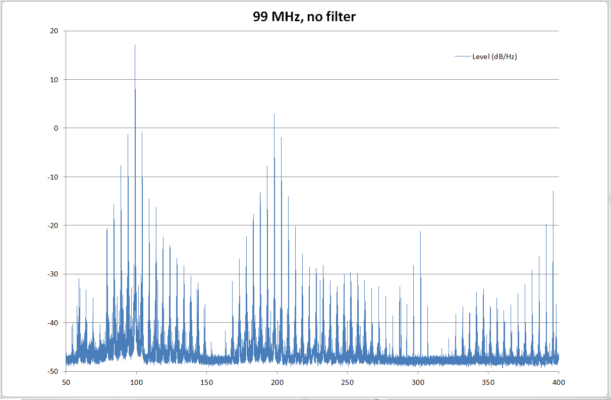
To recap, this is typically the sort of thing that comes out of your Pi when you use it as an FM transmitter:

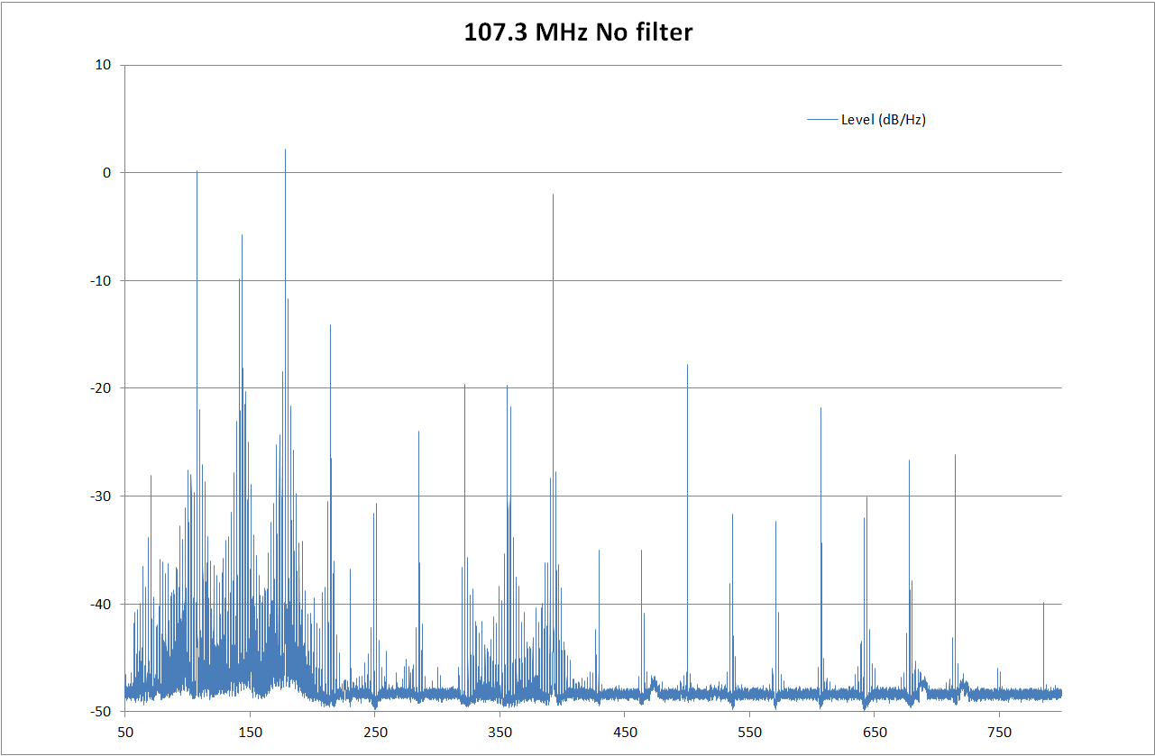
There’s a lovely spike around the 144 MHz mark, which is the amateur radio 2m band. There are probably not many radio hams near me that like the sort of music I listen to. Come to think of it, some times I’m not sure I do either. In general, it’s a broad splattering of crap all over the spectrum. And the Pi’s transmitted output is just as bad, ho ho ho. Ahem. This is the sort of thing we need:

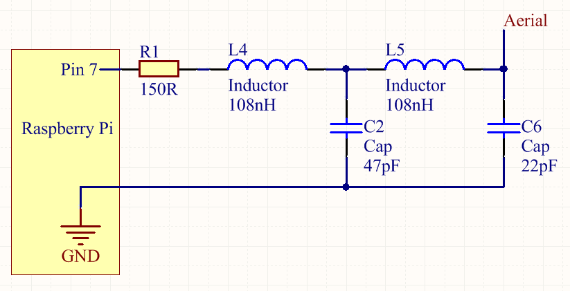
You might notice R1 there. The GPIO pins are not designed to drive inductive or capacitive loads, so we need to make the filter input a bit more friendly. The easiest way is to put a resistor between the Pi and the filter’s inductor. I’ve tried it and it works, but it does reduce the range of the transmission. If you want to try it without R1, don’t blame me if you fry your Pi. There’s about 5 dB loss with this design, which might be fine for you. For me, it reduced the range just enough that the signal was fading out if I stood in the wrong part of the kitchen. The solution was either to avoid using the fridge or to amplify the output a bit.

I’m not an expert with RF circuits (although I probably know more than you), so I used the interwebs to find a design that would

  • Be cheap
  • Work on a 5V supply
  • Not require any fine tuning
  • Be cheap
  • Be easy to make
  • Not have any expensive components

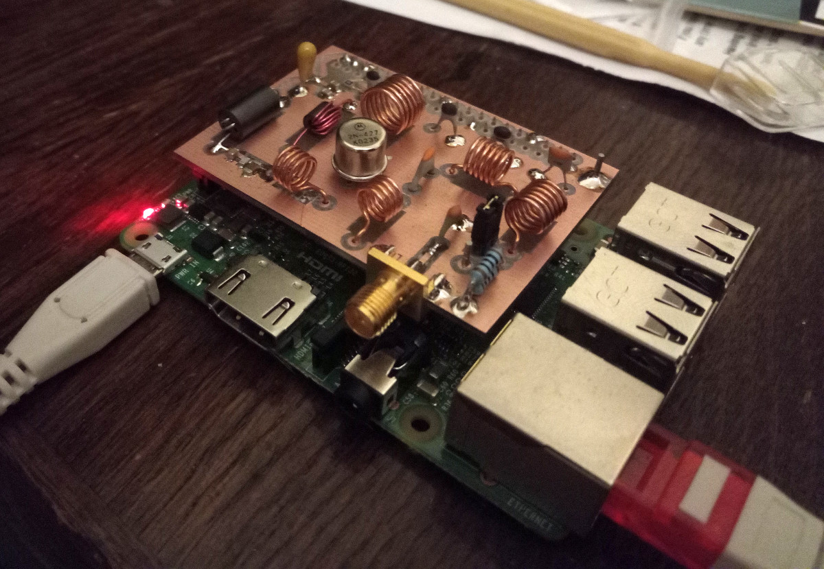
You can probably tell what my priorities were. This was the prototype:

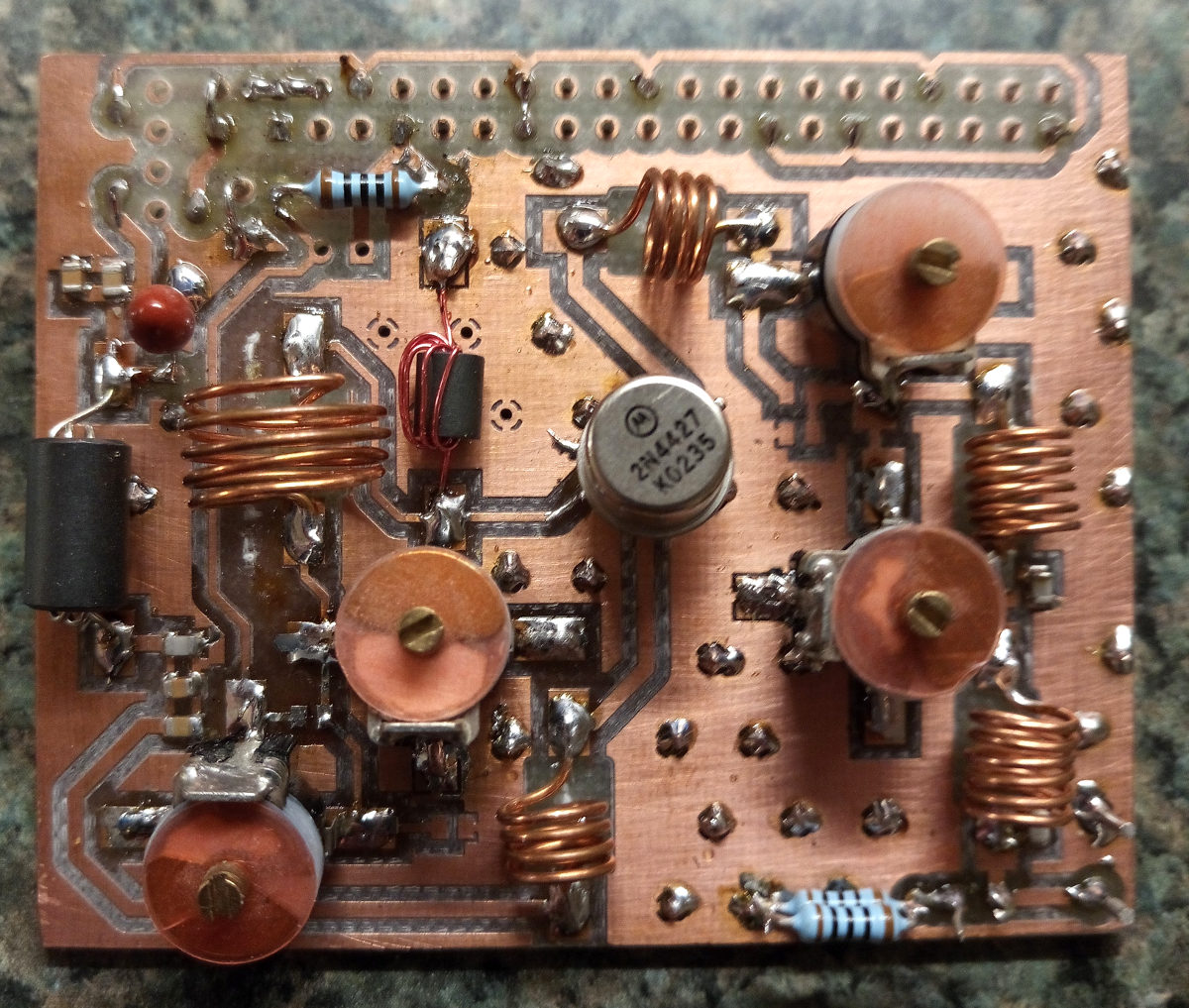
Those with a keen eye have probably already spotted that it looks shit. Bear in mind that it’s already been bodged around a bit, and it looked worse than that by the time I’d finished experimenting with the poor thing. It is a single stage class C amplifier with a low pass filter on the output. The 2N4427 transistor is old and cheap; I bought 5 from China for about £3. Everything else (apart from the variable capacitors) is bog standard and the coils are easy to wind. The variable capacitors are stupidly expensive – there is about £20 worth of them in that photo, so they had to be replaced with fixed ones that cost pennies.

The end result was this circuit:

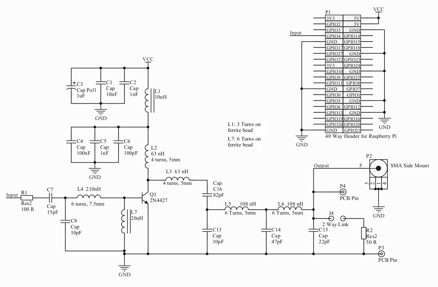
Pi Hat Filter – click to enlarge.

It’s cheap, simple and it works quite well. This is the finished hat installed and working:

This is the output with the filter hat on:

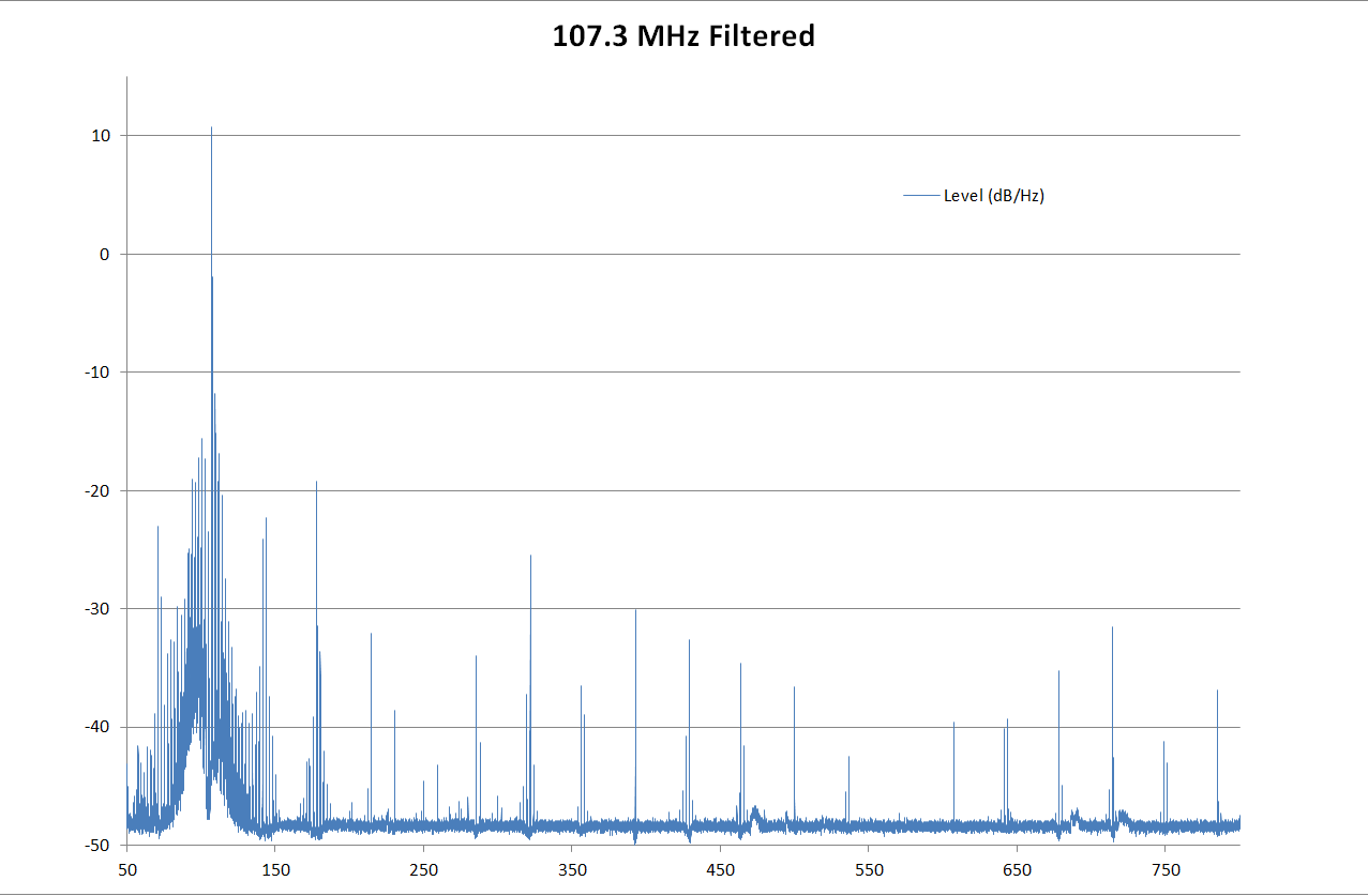
Out of band signals are attenuated by at least 20 dB, which means they are 1/100th the power of when it was hatless. There is even a little bit of gain at our broadcast frequency, which also amplifies the in-band harmonics, unfortunately. It’s not exactly BBC quality but it should stop you annoying the neighbours. If you want to get the absolute maximum performance out of the filter, use 5-95pF variable capacitors instead of C7, C8, C13 and C16 and keep tweaking them until it becomes apparent that you aren’t really having any effect.

The design files are here.  If you would be interested in a kit of parts or a ready made hat, leave a note in the comments and I’ll look into it.

I’ll leave you with a comparison of the filtered (orange) Vs. unfiltered (blue) Pi:

Good, eh?

Taming the PiFM Transmitter (Part 1)

Saturday, March 17th, 2018

One of the million things you can do with a Raspberry Pi is using it as an FM radio transmitter. It is stupidly easy; you just attach a 700 mm long wire to pin 7 and install one of the many variants of the original program which was hacked together at a code club meeting. And now you are a radio pirate. This guide is aimed at those who can do the above but don’t know why it might be a bad idea. If you already know about harmonics or know that they are bad but  don’t care why, you can skip to the next post which is about adding a filter to your Pi.

At this point it is traditional to say that broadcasting without a license is illegal in most countries and doing something like using your Pi to stream internet radio stations to the analogue radio in your kitchen is wrong and makes Eben Upton cry.

One thing you will often hear in discussions about Pi radio is that lots of unwanted harmonics are produced on frequencies other than the one you are broadcasting on. These can interfere with legitimate users of that frequency; for example a passing pilot might not want to hear the Crisp Biscuit Breakbeat remix of Josh Wink’s Higher State of Consciousness instead of the control tower telling her where to land. You might think that anything broadcast from your little Pi won’t be powerful enough to interfere with a professional communications system, and you are very probably right. But what exactly is coming from our Pi’s aerial? This is what we would like to see:

What we would like to see coming out of our Pi. Click for a better view.

Along the X axis are all the frequencies from 50 MHz to 350 MHz. The Y axis shows the level of the signal at that frequency in dB. If you just clicked on the “dB” link and are none the wiser, the upshot is that the dB makes it easy to compare the relative powers of signals. For example, a +3 dB difference is twice the power and a -3 dB difference is a half the power. So +6 dB means the signal is quadruple the power of whatever you are comparing it to – it’s the same as a +3 dB doubling and another +3 dB doubling. As the dBs go up in linear fashion, the corresponding power goes up exponentially: +3 dB, +6 dB, +9 dB corresponds to x 2 power, x 4 power and x 8 power.

The graph shows the main peak of our transmission at 107.3 MHz, at about +11 dB, a harmonic at 214.6 MHz at -25 dB and another at 321.9 MHz at -30 dB. These unwanted harmonics are bad, but their levels are a lot lower than the main broadcast frequency. If the harmonic’s signal level is -36 dB compared to the main one, it means it’s about 4000 times weaker and we don’t really need to worry about it, given that the main signal only goes a hundred metres or so. The other unwanted signal is even lower: -41 dB compared to the main signal so I’m not even going to bother to work out the exact value because it is so small. OK, it’s 12,500 times less than the main signal. That won’t even make it out of the room.

So that’s our ideal transmitter, with a nice strong signal on the frequency we want and weaker signals on the frequencies of the harmonics we don’t. How does this compare to the actual signal from a Pi? Take a look at this little beauty – it is what’s coming out of my my Pi when it’s broadcasting on 107.3 MHz:

Actual output from a Pi. Barf.

It’s spewing crap from 50 MHz to 800 MHz and probably beyond. One of the harmonics is actually more powerful than the frequency we want to transmit on. The signals coming out of that aerial are dirtier than a dog in a field of incontinent cows [todo: change this to something more tasteful]. The neighbours are probably wondering why old skool breakbeat trance music is coming out of their hoover.

It gets worse though. The harmonics coming from the Pi change in number, size and position as you change the frequency. Broadcasting on exactly 100 MHz actually produces a graph somewhat similar to the first one, but drop the frequency by 1 MHz to 99 MHz and you get this:

99 MHz – Craptastic!

Now that is quite pretty, but it did genuinely start making lines go down my monitor and a hum come out of my speakers. God knows what it was doing to the output electronics in the poor Pi.

So, before doing anything else, you need to pick a frequency that won’t make music come out of your granddad’s fillings. The cleanest one is 100 MHz, but where I live there’s already a commercial station there, so that was out for me – my little Pi couldn’t compete with the big boys. You don’t want to pick one that’s close to 100 MHz either because they seem to be the dirtiest. Trial and error, picking the gaps between existing stations, seems to be the way to do it. Ideally, you want a spectrum analyser like the one I used to make the graphs, and surprisingly, you can get the hardware for about £20, and use something like this to turn it into a spectrum analyser. At the very least, you could pick a frequency and see how many times your broadcast appears when you tune your radio up and down. As a general rule, the fewer times the better.

But however carefully you choose your frequency, your Pi will still be broadcasting all over the spectrum and possibly making someone near you very angry. You can improve things by putting a filter on its output, and I can show you how in the next post.